
This article was written in the 1980s but little seems to have changed since then, except that BMW and YAMAHA have produced road models using systems mentioned herein, and the Britten has achieved racing success with a plastic "Hossack style" front end. Not to forget the Bimota Tesi and Vyrus.
.© 1986 -- 2002 Tony Foale
Over the past few years we have heard much about a new generation of front suspension systems, usually with the promise that soon all motorcycles will be built this way or that. In particular, the Cortanze designed, Elf sponsored machines have been the favourite examples of most writers, conveniently forgetting the earlier (c. 1968) systems from the British engineer, Jack Difazio, whom history may well remember as the instigator of the present interest in alternative steering systems. However, as with most engineering ideas in general and motorcycle ideas in particular, there is little that is really new. Interest in a wide range of steering designs is as old as motorcycling itself. Although, only a small number of designs have ever been accepted for quantity production. The girder fork was the early favourite, being used by most manufacturers at one time or another.
There were always dissenters though, the Neracar used a hub centre design and O. E. C. had another unusual system, both were known to give excellent results by contemporary standards. But by the early 1950's, hydraulically damped telescopic forks were becoming well established, mainly due to their improved ride over the undamped or friction damped girders. Some manufacturers, however, were even then aware of the deficiencies of teles. and used some form of link forks, e.g. BMW went for the British designed Earles fork, even though they had been pioneers of teles. Ariel on the other hand used pressed metal trailing link forks on their Leaders and Arrows.
So, is there really any significant problem with the forks that have adorned our bikes for so long; do the designers of the alternative proposals know something that eludes all others? Well, there are problems with normal forks, and these begin to show up more as modern bikes get heavier and more powerful. All the normally used types of front suspension/steering systems have a common feature, they all mount on and steer through a steering head. So what, you may rightly ask?
The sketch shows how any lateral flex in the fork legs allows the tyre contact patch to move away from the steering axis. This really matters, because wobbles can be caused or greatly increased by this misalignment, both on fairly smooth roads at a particular speed, and at any speed on a more bumpy surface. Consider what happens when the wheel glances a bump to one side, the forks deflect away from this bump and if still deflected when the next bump is hit, the force of this will produce a torque about the steering axis that will cause the forks to steer to one side. We have all experienced this to some degree, sometimes it amounts to nothing more than a minor handle bar shake, but in far too many cases it can develop into a frightening tank slapper with occasional fatal results. However, if the tyre contact patch was held rigidly in line with the steering axis, then little torque would be applied to the steering, and the suspension would be free to do its job of absorbing the bump forces, with the minimum of drama or awareness from the rider. There are many other problems that stem from the use of head stock mounted forks, but this potential for lateral flexibility is the single most important one.
Another disadvantage is the large amount of leverage that can be exerted on the steering head itself. This results in very large forces that have to be resisted by a strong and hence heavy frame. In addition, telescopic forks are well known for their propensity to nosedive under the influence of braking forces, encouraging the current solution of increasing the damping to slow the rate of dive. (This subject of dive will be considered in depth, next month.) Poor response to small bumps, such as expansion joints in the road, which may be due to stiction in the sliders is another frequent complaint aimed at telescopics.
So now we know why the conventional setup can cause problems, but do any of the new (or old) fangled systems really offer a viable and cost effective solution? For make no mistake, unless an alternative can be economically mass produced, there is no chance of seeing it fitted to standard roadsters, no matter what technical or safety benefits are on offer. I believe that some of these schemes have substantial potential, but whether this is translated into practice, depends on the standard of detail design and manufacture. It is no good comparing a set of top quality teles with a badly constructed hub-centre arrangement. There are those magic words, again, "HUB-CENTRE", what do they mean and should all these different designs be labelled as such?
It seems to me that there are two main classes of these alternatives, the first, like the Neracar, the Difazio and the Bimota Tesi which all have the main wheel support at, or very near to, the wheel centre. It is these that can reasonably be termed 'hub-centre', although the actual steering mechanism is not at the centre. The second class includes the Elf.e, the Hossack, my own design used on the Quantum, Parker and others. At the moment, there does not seem to be a satisfactory generic term to cover these systems. The best I have to offer is double link or double wishbone, but not all use a wishbone as such, more like a pivoted arm, some suggest the term, parallel link, but there is no need to have them parallel. Let's look at some of the systems in more detail and see how they do the job.
Generally a large diameter, steerable but non-rotating hub is mounted on a king-pin located within it. Another hub, of larger diameter, and forming part of the wheel, is mounted onto the first hub via large ball races. The centre line of the king-pin defines the steering axis, and so the only flexure that can allow the tyre to deflect away from this axis, is in the wheel and the hubs themselves, but as we must also have these components with a conventional design, it can be seen that virtually all the other sources of compliance, in the forks, have been eliminated at a stroke. It must be remembered though, that any wear or play in the king-pin bushes or bearings will permit the dreaded lateral displacement, play in bushes has a different effect from that due to flex, and is generally more detrimental to stability. This is what I meant by the importance of detail design. Consider now, some actual examples and study their pros and cons.
This is the design that most readily comes to mind when hub centre is mentioned. It incorporates the features mentioned above, but the king-pin is in the shape of a cruciform and is free to rotate on the axle. To prevent free rotation (except the small amount needed for suspension movement) the inner hub is connected upward to the steering links via an "A" frame on each side, the two being joined above the tyre by a crossmember. The brake calipers are mounted on these A frames and their torque reaction is taken by the steering arms. The axle is held between the open ends of a forward facing swinging arm, which must be wide enough to give tyre clearance as the steering is turned. Suspension units are connected to this swing arm, and the suspension loads are carried through the king-pin bushes. Overall this is quite a clever design mechanically but not aesthetically, and remember that it was patented nearly twenty years ago. As mentioned above the source of lateral compliance (relative to the steering axis) is reduced to that of the wheel, wheel bearings, and the king-pin bearings. Braking loads are spread between the bottom swing-arm and the top steering links, and because of their distance apart and proximity (compared to a head-stock) to the tyre contact patch, the loading is much less than that normally experienced.

Disadvantages also exist; as might be expected, we seldom get anything for nothing. As all the sideways rigidity is provided by the king-pin, this part is quite highly loaded when the wheel is subject to a lateral force, e.g. hitting a bump whilst cornering. The potential strength of the side 'A' frames is not used to relieve this loading, which also tends to bend the axle into an S shape, and twist and bend the swing-arm. However this axle and swing-arm distortion does not allow the front tyre to misalign with the steering axis (because the axis moves with the wheel). Perhaps another problem is that it is a fairly complicated system, both in terms of the number of required components and also in terms of wheel changing ease.
On some of their endurance racing bikes ( Nessie amongst them ), this team experimented with variations on the Difazio theme. One such design replaced the king-pin with a spherical joint that was free to pivot in all directions, to prevent the sideways movement thus made possible, a triangulated wishbone was connected to the middle of the cross piece joining the tops of the 'A' frames. A single suspension unit was mounted on the top of the wishbone, relieving the hub pivot of suspension loads. Although the axle is still subjected to bending loads from braking, this system removes those due to lateral and suspension forces, and in addition, the possibility of swing-arm twist is eliminated. So far so good, but the potential for misalignment between the wheel and the steering axis is increased, flex in the 'A' frames can now add to that. Despite this, I think that these modifications to the original have potential.
Probably the most recent of the hub-centre designs, this has some features in common with the Defazio, although the king-pin is fixed to the axle and not free to rotate on it. Consequently the braking forces are taken through the wheel spindle to short brackets, fixed to each end. These brackets are in turn located by two torque arms. Because these arms are relatively close to the swing-arm the forces are high compared to the Difazio setup. The king-pin/axle is much more highly stressed, and cannot be rigidly clamped in the swing-arm, instead it must be free to rotate within it, to allow for vertical wheel movement. Hence, the spindle cannot add to the torsional stiffness of the swing-arm, which needs to be bigger as a result. Hydraulic steering, heralded in many press reports as a major innovation, is really just another source of potential problems, as they seem to have discovered. It is difficult to see any benefits which outweigh the disadvantages. Anyone with experience of such closed circuit hydraulics would realize that provision for expansion and piston rod displacement is necessary. It appears that Bimota did not, until reminded in rather dramatic fashion. The solution adopted was the provision of a pressurized gas chamber, separated from the oil by a flexible diaphragm, similar to many suspension units. Unfortunately, the compliance thus introduced may cause sponginess in the steering. Small wonder then, that some of those to have ridden it, have been less than optimistic about the feel of the machine. I have been told that it is definitely not confidence inspiring. One could be forgiven for thinking, that Bimota would have been better off copying Difazio's mechanicals, and using their Italian flair to transform the visuals. Press reports indicated that the TESI was designed as a college project, as such it is to be commended but it is far from a practical proposition it it's first presentation.
( 1997 note ) The design of subsequent Bimota front ends has changed considerably since the first version, improving the areas of doubt mentioned above.
This type generally, is mechanically simpler, comprising basically an 'upright' (car terminology) to which the wheel and its bearings are attached. This upright is held in place by two forward facing pivoted arms or wishbones, the front ends of which allow for steering and suspension movement. Structurally, the various designs within this family differ mainly by the locations on the upright to which the two pivoted arms are attached. Considering the lateral stiffness characteristics, we see that this is dependent only on the stiffness of the upright and the wheel. Let's look at some actual systems.

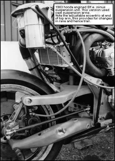
Elf. e (also similar to Dider Jillet). photo1 photo2
Here the upright is fairly short, and hence light-weight and rigid, but this necessitates that the two pivoted arms have their forward ends within the wheel circumference, which in turn means that they have to be curved outward for tyre clearance on full steering lock (to one side), the steering drag link must also be widely spaced for the same reason. So, even though it would be hard to design a more efficient upright, the pivoted arms have somewhat less than the optimum shape. A fact aggravated by the need to carry the suspension forces through one of them. This introduces torsional and vertical bending loads into that arm, which must then be large enough to handle them.
( 1997 addition ) Later versions of the Elf. went away from this design completely and used a system somewhat akin to a car style "McPhearson strut". Despite the fact that in the hands of Ron Haslam this setup began to do well, I think that the original system had more promise. Measuring steering and link geometry from photos I am of the opinion that it was in this area that a rethink was needed.
This is the antithesis of the above, within the double link family. Instead of a very small upright with large curved arms, this setup has a larger upright which is located by very light and stiff wishbones. These are mounted above the tyre. Although the upright is constructed in the form of a fork, which allows for the use of normal wheels and brakes, there is no reason in principle why this could not be a single-sided component, to give the quick wheel changing of the Elf. e. But the stiffness to weight ratio is probably better with the fork.
Compared to the Elf. this design has both advantages and disadvantages. The steering joints are mounted higher , the increased leverage causes greater loads in the spherical pivot bearings, and the potential for using the engine structurally as the main frame (exploited by the Elf. ) is reduced, simply because of the required physical location of the pivots.
In common with the hub centre schemes the Elf. has limited steering lock, but on the other hand the Hossack type is free from that constraint and as such is the only system, described here, that has any real potential for off-road use.
( 1997 note ) Ollie McKan in America developed a system for off-road use, this seems to use a suspended headstock, allowing the main suspension loads to be fed directly into taper roller bearings. This type of design has the added advantage that steering friction is reduced compared to steering through a sperical bearing subjected to suspension loads.
The New Zealand based Britten racing team has achieved considerable success with bikes fitted with this type of front-end. The main upright / fork is made from a carbon fibre composite as are many other components on the machine.
Perhaps I should not comment on my own design, but I will try to be objective. This combines features of both the previous systems. The lower arm is curved and at hub height, like the Elf. , but the upper one is a wishbone above the tyre, like the Hossack. WHY? Well, by increasing the distance between the upper and lower arms (compared to the Elf.), the loads fed into the pivot bearing are considerably reduced. The suspension unit can now be fitted to the top arm near the upright, thus eliminating torsional and vertical bending loads in the lower curved arm. This component can now be made thinner and lighter. The price paid for this, is that the upright must be longer, and hence heavier and/or less stiff. On balance it was my opinion that it was a better compromise, as it also allows the steering drag link to be above the wheel where it is closer to the handle-bars, thus simplifying linkages, and need not be mounted wide to clear the wheel on full lock. The Parker system differs from mine in that the steering mechanism does not employ a drag link, instead it uses a kind of telescoping torsion tube to pass the rider's messages on to the wheel.
( 1997 note ) With the help of Parker this is the system adopted by Yamaha for use on their road bike.
To close I would like to take a quick look at the Saxon / Motodd system. This has been left out of the previous discussion, solely because it does not fit into either of the two categories considered, using just one pivoted link and a fixed pivot at the top(it is really an improved form of telescopic fork). Because one pivoted link is insufficient to fully locate the fork, this is further supported by two stantions, the fork being free to slide on these as with normal teles. Although the suspension function is handled externally by a separate spring/damper unit. The steering axis is defined by the line drawn through the upper fixed pivot and the lower moving one, which is attached to the fork, thus the length unsupported is kept to a minimum. In some ways this design is an adaption of a "McPhearson strut" to bike use, although the overhang from the wishbone to the wheel is much greater than is usual in the car version.
I believe that one of the main design criteria, was that it must look similar to telescopic forks, in the belief (rightly or wrongly) that the market would respond better to such a design. Viewed in that light, I see it as a considerable potential improvement over normal forks, though not as great as that offered by the other designs.
( 1997 note ) This is the basic system chosen by BMW for some of their current models.
SUMMARY
I have shown that the location of the wheel relative to the steering axis is not dependent on the stiffness of the pivoted arms, for either the hub centre variety or the double link type. But the rigidity of these arms is still very important, because any flex allows the steering axis to move out of line compared to the rest of the bike, including the rear wheel. To put it another way the REAR wheel can move relative to the steering axis. This is less important than the front doing likewise, but is still to be avoided. However, these alternative steering systems may in practice, also locate the rear wheel in a more positive manner. The lower mounting points (compared to a normal headstock), for the connection of the front setup, are closer to the rear swing arm and hence the chassis may be stiffer, but in addition the loads fed in are smaller, thus further reducing the amount of flex.
In this article we have really only considered the stiffness characteristics of these newish suspension systems, there are other aspects to look at as well. Next month we can look at the anti-dive properties and how that works. Steering geometry is also important and in a later article I'll describe experiments that I made to evaluate various possibilities in this regard.